Quay Crane
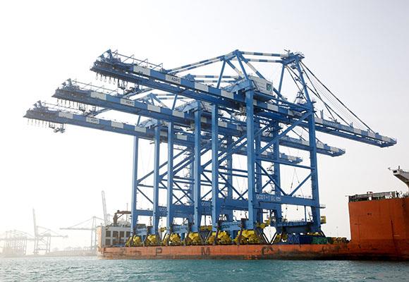
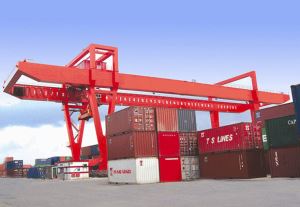
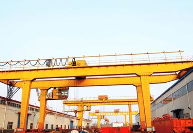
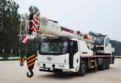
Quay crane is widely used to load and unload containers from ship and trucks. The crane frame design is very advanced so that the crane can work with a high efficiency. The trolley can travel on the rails which are mounted on...
Guay Crane
Description
The Guay Crane is widely used to load and unload containers from ship and trucks. The crane frame design is very advanced so that the crane can work with a high efficiency. The trolley can travel on the rails which are mounted on the outreach beam and the whole crane travels on the rails mounted in the ground. The fast moving and lifting speed brings you excellent working performance.
The Quay Crane is widely used to load and unload containers from ship and trucks. The crane frame design is very advanced so that the crane can work with a high efficiency. The trolley can travel on the rails which are mounted on the outreach beam and the whole crane travels on the rails mounted in the ground. The fast moving and lifting speed brings you excellent working performance.
Quay Crane is mainly consisted of steel structure, hoisting mechanism, trolley travelling mechanism, long travelling mechanism, luffing mechanism. All the mechanisms can be operated with a stepless speed by the operator in the omnibearing view cabin.
Features
1. Rated load lifting capacity (t/h ): 400, 500, 600, 800, 1000, 1250, 1500, 1800, 2000, 2250, 2500, 3000, 3600, 4000, 4500, 5000.
2. Rated load lifting capacity priority ( t ): 10, 12.5, 16, 20, 25, 32, 40, 45, 50, 56, 63, 71, 80, 90.
3. Working Level:
Standard | GB3811-2008 |
Use Classes | U8 |
Load-up Condition | Q4 |
Work Level | A8 |
4. Working Level of Mechanisms:
Mechanism | Using Grade | Load-up Condition | Work Level |
Lifting/Closing | T8 | L4 | M8 |
Trolley | T8 | L4 | M8 |
Crane | T5 | L3 | M6 |
Front Girder Pitching | T4 | L3 | M5 |
Cab | T4 | L3 | M5 |
5. Working Speed:
Mechanism | Speed ( m/min ) |
Lifting/Closing ( full load/without load ) | 60~80/100~240 |
Trolley Traveling | 100~280 |
Crane Traveling | 20~40 |
Front Girder Pitching | 5~10 ( one way ) |
Cab Traveling | 20~25 |
6. Steel Structure:
Design Service Time | 20~30 years |
Load Character | Consecutive, heavy-duty, alternating |
Operating Character | Cycle operation, work busy, high impact |
7. Components of Steel structure: crane chassis, back pull rod, tower frame, front pull rod, front girder, gantry frame, funnel scaffold, angling strut, back girder.
Specification
Lifting Capacity( below spreader ) | t | 30.5 | 35 | 40.5 | 50 | ||
Lifting Capacity( above spreader ) | t | 38 | 45 | 50 | 60 | ||
Work Level | A7 | A7 | A8 | A8 | |||
Span( m ) | S | 10.5 | 10.5 | 22 | 22 | ||
Base Distance | B | 16.5 | 17.63 | 16 | 16 | ||
Lifting Height( above/Below) | H1 | 22 | 22 | 28 | 38 | ||
H2 | 16 | 10 | 14 | 14 | |||
Speed | Lifting Speed | Full Load | m/min | 46 | 30 | 50 | 70 |
Only With Spreader | 120 | 60 | 120 | 150 | |||
Trolley Traveling | 150 | 120 | 120 | 220 | |||
Crane Traveling | 45 | 25 | 45 | 45 | |||
One Luffing Time Of Jib | min | 7 | 6 | 5 | 5 | ||
Main Dimension | L1 | 38000 | 30000 | 38000 | 55000 | ||
L2 | 10000 | 10000 | 11000 | 18000 | |||
L3 | 4000 | 8850 | 6000 | 6300 | |||
L4 | 4000 | 110000 | 15000 | 20000 | |||


